Nixie IN-1 Clock
Nixie IN-1 Clock
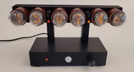
A 6 digit Nixie clock.
Features:
- (6) IN-1 Nixie Tubes with Sockets
- (5) INS-1 Nixie Bulbs
- Nixie Lifespan Maximization
- GPS Disciplined Primary Timebase
- Accuracy: ±1 Second
- Automatic Time Setting
- Single Rotary Encoder Interface
- Motion Sensor
- 12V 1A Power
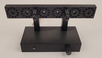
- 3D Printed Enclosure
- Modular Design
Design Documents
| Schematic Diagram - Controller Board | nixie_IN1_schematic.pdf |
| Schematic Diagram - Backpack Board V1 | Nixie Backpack I Schematic.pdf |
| Schematic Diagram - Backpack Board V2 | Nixie Backpack II Schematic.pdf |
| 3D Print Files | nixie_IN1_mechanical.zip |
| Source Code - Arduino (clock controller) | Arduino.zip |
| Source Code - PIC12F1822 (backpack V1) | pic12f1822.asm |
| Source Code - PIC16F1615 (backpack V2) | pic16f1615.asm |
Operation
| Power Supply | Requires 12V 1A DC |
| Power Bulb | Always on |
| Digit Tubes | Auto shutoff after 30 minutes of no motion |
| Punctuation Bulbs | On with Digit Tubes when GPS time signal is locked on |
| Knob Turn | Test digits, automatically returns to time display |
| Knob Press | Turn knob to change the UTC to local time offset |
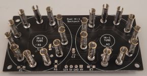
Dual IN-1 Backpack
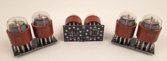
The clock is built using three Dual IN-1 Backpack modules and a main controller board.
Each Dual IN-1 Backpack has a microcontroller and the drive circuitry for two IN-1 tubes.
The backpack is supplied with +5V, +170V, and controlled via a serial interface.
The serial interface is 9600 baud receive only, and all the backpacks are connected in parallel.
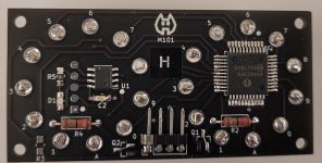
There are two versions of the Dual IN-1 Backpack.
The first version uses a Microchip HV5622 and PIC12F1822.
The HV5622 is a high voltage shift register with latch, which works great because the outputs all change simultaneously.
This makes the software easy.
The HV5622 chip is rated for 12V and can switch high currents;
however it was found to work at 5V as long as it's switching low currents, which is enough for the Nixie tubes.
It won't quite work at a lower voltage; it starts dropping out right at 3.3V.
This design also includes some anode switches (Q1 and Q2), which are not really needed, so they have been bypassed.
However HV5622 is an expensive chip and a little difficult to solder, so the design could be improved.
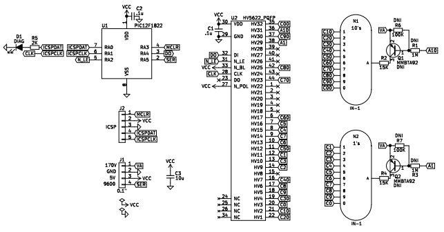
Code for this design
The second version uses a Microchip PIC16F1615 and discrete transistors.
This design cheaper and easier to solder by hand. Plus it operates at 5V or 3.3V
The design lacks the latch capability, but this makes no practical difference in the display performance.
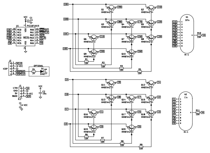
Code for this design
Each backpack is assigned an ID from A to Z. In this clock the backpacks are designated 'H', 'M', and 'S'. The backpack ID is set by connecting one backpack at a time and issuing the special command ATID=X, where 'X' is the ID (A to Z). The ID is stored permanently in the backpack.
Backpack display commands consist of 3 characters; the ID followed by two digit values.
If the ID is lowercase then a fade is performed (a cross fade from the current number to the next).
Special ID characters '@' (immediate) and '*' (fade) address all backpacks.
Examples:
@-- (blank both digits in all modules instantly)
H12 (set module 'H' to '12', instant)
h12 (set module 'H' to '12', with fade)
H12M34S56 (show "12:34:56" instantly)
The tube "sockets" are rather disappointing. Modified Molex (02-09-1102/4) connectors are used as tube pin sockets. They are a little too small so some rework is needed to make them fit. Plus they aren't designed to be tube sockets in the first place, so it's impossible to make them fit really well. But they do barely work and the tubes are removable.
5V Backpack Nixie Power Supply*
The Dual IN-1 Backpack normally requires a high voltage power input for the Nixie tube.
To run from 5V, this piggyback power supply can be used;
it produces about 185V at 5mA, which is enough for two IN-1 tubes.
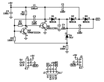
This makes a 5V-only dual IN-1 module.
The voltage regulation is not great. This is how it performs at various load levels...
| vIn | mAin | Vout | mAout | Efficiency |
| 5.0 | 20 | 210 | 0.0 | No load |
| 5.0 | 150 | 188 | 3.0 | 75% |
| 5.0 | 260 | 186 | 5.4 | 77% |
| 5.0 | 420 | 182 | 8.9 | 77% |
Bill of Materials
| Part ID | Quantity | Description | Size | Part | Source |
| C1,C4,C5 | 3 | 1uF 100V capacitor | 1206 | 100VDC 1uF 20% | Mouser 963-HMK316BJ105ML-T |
| C2 | 1 | 100uF 6.3V capacitor | 1206 | 6.3VDC 100uF | Mouser 963-JMK316ABJ107ML-T |
| C3 | 1 | 47pF 100V capacitor | 0805 | 47pF 0805 5% | Mouser 710-885012007080 |
| D1,D2,D3 | 3 | 100V fast diode | SOT-23 | BAS16 | Mouser 771-BAS16-T/R |
| D4 | 1 | 91V Zener diode | SOT-23 | 91V 225mW | Mouser 863-MMBZ5270BLT1G |
| L1 | 1 | 100uH inducor | 8mm | 100uH 20% 1.1A | Mouser 652-SRN8040TA-101M |
| Q1 | 1 | NPN transistor | SOT-23 | NSV1C201LT1G | Mouser 863-NSV1C201LT1G |
| Q2 | 1 | NPN transistor | SOT-23 | PMBT2222A | Mouser 771-PMBT2222A-T/R |
| R1 | 1 | 750 Ohm resistor | 0805 | 750 Ohm 1% | Generic |
| R2 | 1 | 22K resistor | 0805 | 22K Ohm 1% | Generic |
| R3,R4 | 2 | 100K Ohm resistor | 0805 | 100K Ohm 1% | Generic |
Printed circuit board
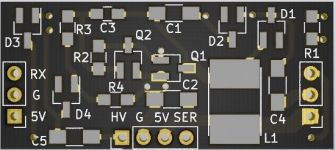
PCB Gerber files for this board
* Credit for the original circuit design goes to The LED Artist.
This clock needs high voltage for 3 dual backpack modules, punctuation bulbs, and a power indicator bulb, so a single high voltage module that can provide at least 20mA at 170V is used.
Clock Controller Board
The controller PCB has the Arduino Pro Mini and a bunch of connectors to plug in all the modules.
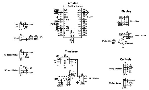
Arduino code for the clock
Nixie Time Display
This clock doesn't have a typical AM/PM indicator.
AM/PM is indicated by alternating 12 and 24 hour time formats every 2 seconds.
The clock punctuation is four INS-1 bulbs, which are normally on when the clock is on. If the punctuation is off that means the GPS signal is not locked on.
The power indicator is one INS-1 bulb, which is always on.
Auto-Shutoff occurs after 30 minutes of no motion detection. All Nixies except the power indicator are shut down. Cathode de-poisoning is performed just prior to shutdown.
Automatic cathode de-poisoning is performed every hour of continuous operation. The display will flash for a few seconds during this process.
User Interface
The user interface is a rotary encoder with push.
- Turn the knob to test the display; it simply turns on all the same digit.
- Press to enter time setting mode, turning the knob adjusts the UTC offset.
Motion Sensor Module
A small PIR motion sensor activates the clock.
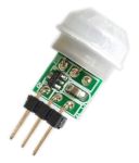
Time Base Module
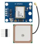
A NEO-6M GPS module provides the primary time base.
The processor takes over timekeeping during periods when the GPS signal drops out.
High Voltage Power Supply Module
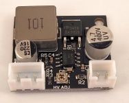
A generic MAX1771 based high voltage module makes 170V for the Nixies.
This tiny module makes just enough current, ~20mA for the clock.
Build Pictures
Interior
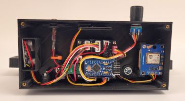
This has a microwave motion sensor, which was replaced with a PIR motion sensor.

